IMaging, mechanical and electrical design
Aerial Imaging System
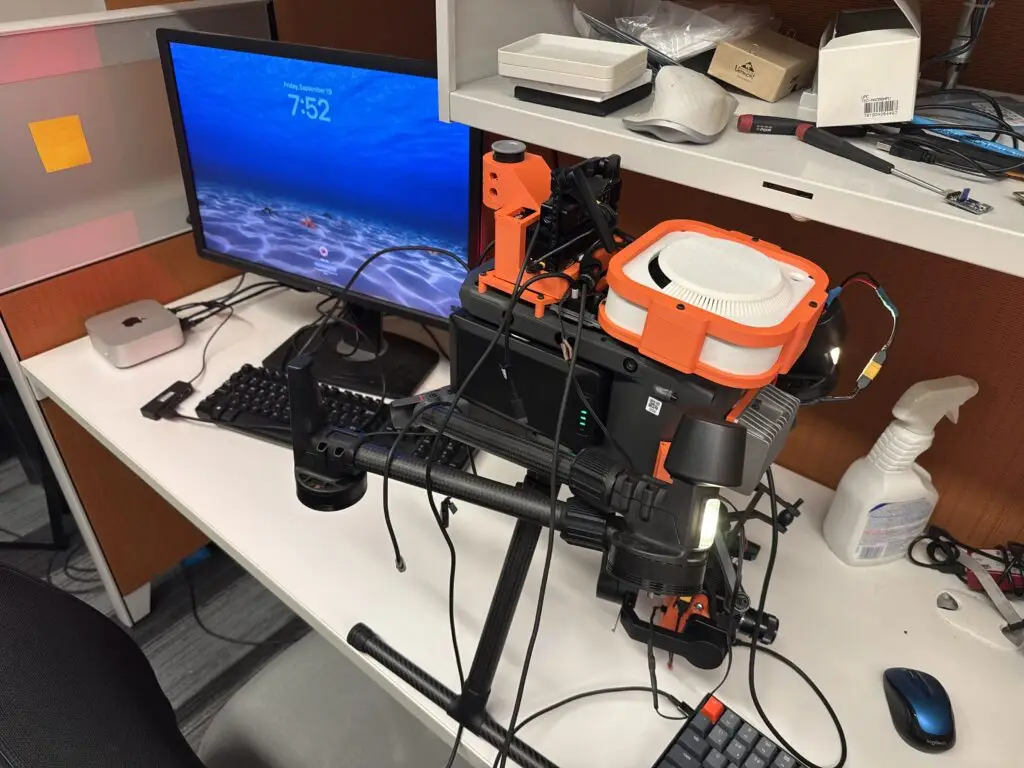
Due to my interest in agricultural imaging, my first project involved an existing industrial drone that hadn’t been worked on in a while. My job was to build up the electrical and mechanical foundation required for an onboard, standalone imaging system to be powered directly off of the drone.
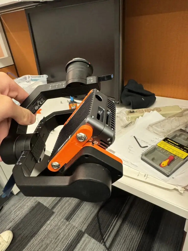
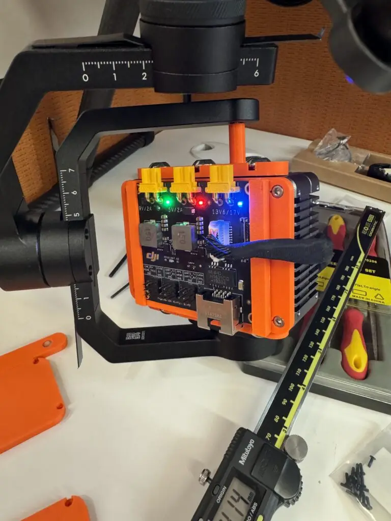
My first course of action was adapting our lab’s cameras to the drone’s gimbal, requiring a few test prints to ensure the right fit and tolerances. Once the camera was correctly mounted, I found and mounted a DJI power distribution board to the camera. Using the XT-30 outputs, I spliced a barrel jack to an XT-30 cable to output directly to the camera, carefully testing using a multimeter.
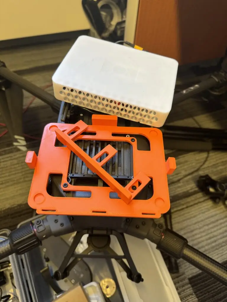
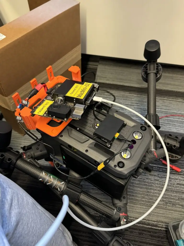
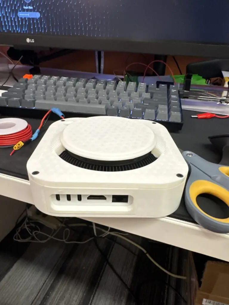
The next steps were to begin working on mounting a Mac mini to the drone. To reduce the size of the Mac mini, we removed some of the redundant hardware and used an open-source design to minify the mini. I had to find a power solution that could directly power the Mac mini from the drone’s DC power outputs, and ended up using a weather-proof buck converter off of Amazon. Confirming everything with the multimeter, we hooked up the Mac mini to the drone and confirmed operation.
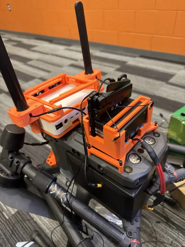
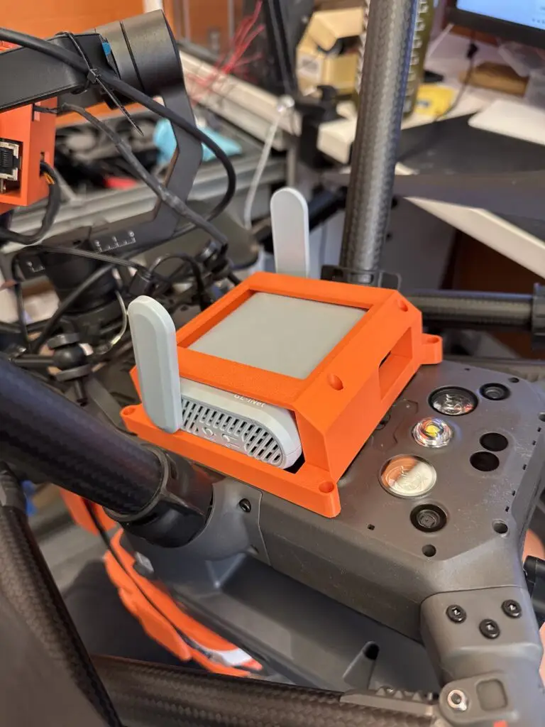
Next, I began work on adding the other required materials to the drone. Some form of communication between the onboard Mac mini and some ground station was required. In that case, the onboard Mac mini needed some form of internet access. I decided that a mobile hotspot could do the trick, and began work on integrating the hotspot onto the drone, powering it off of the Mac mini USB-C outputs.
I added some fans for ventilation for the Mac mini, powering the fans off of the same 12V output from the buck converter. With everything assembled I ran some initial tests with the drone grounded and without the propellers installed.
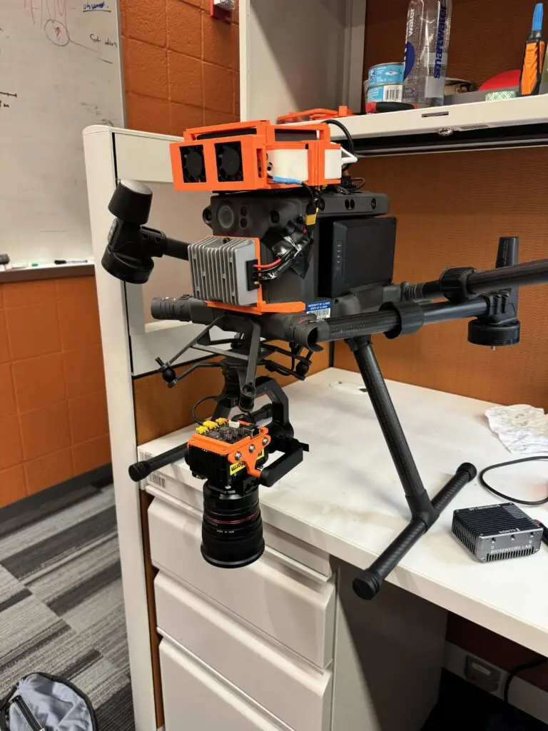
Unfortunately, we ran into some gimbal issues. Aside from the lens being much too large for the gimbal motors, the current model of gimbal was outdated, and regardless of the updates we tried to install, it refused to respond to remote controller inputs. When debugging, another student realized that the gimbal required a “load” signal to be continuously received according to documentation. Using a DJI Manifold, we were able to successfully register the gimbal with a DJI account, connect it to our remote controller, and then achieve some level of functionality. I designed several parts to attach the Manifold to the drone body, as well as the wiring.
I still had some work to do, we ran into a few issues with the Mac mini we were using. As a result, I designed a new case for a M2 Mac mini we had in the lab, also removing the internal power supply to directly connect it to the buck converter. Our router also was not delivering the expected outputs. Instead, we switched over to a mobile router as a WiFi extender, and then connected this to the onboard Mac Mini. I designed a mount for this and attached it to the underbelly.
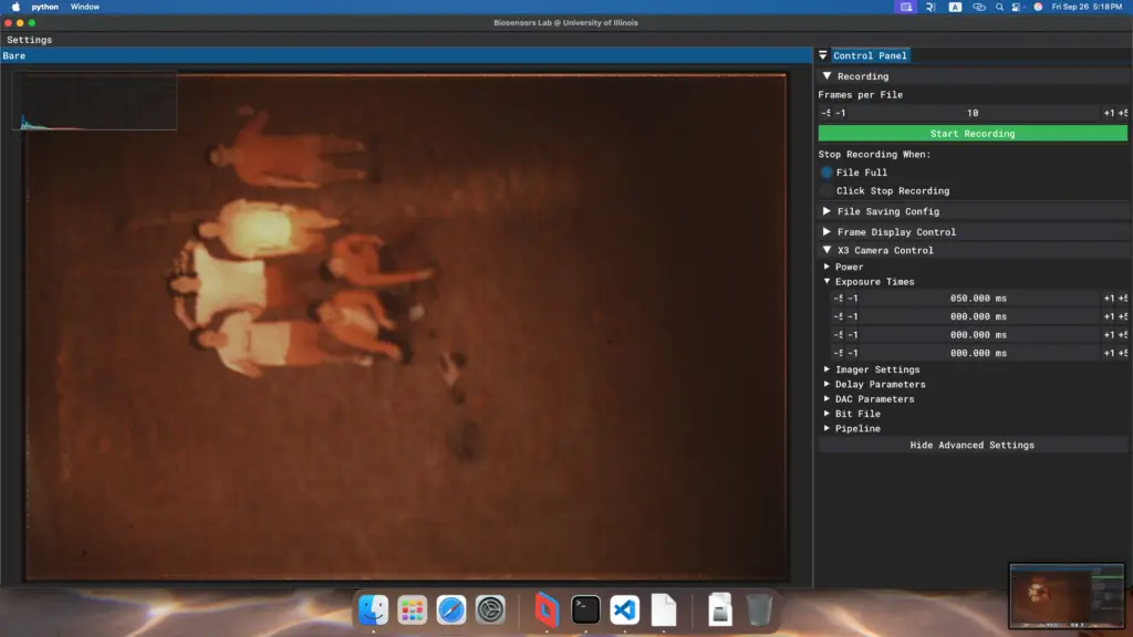
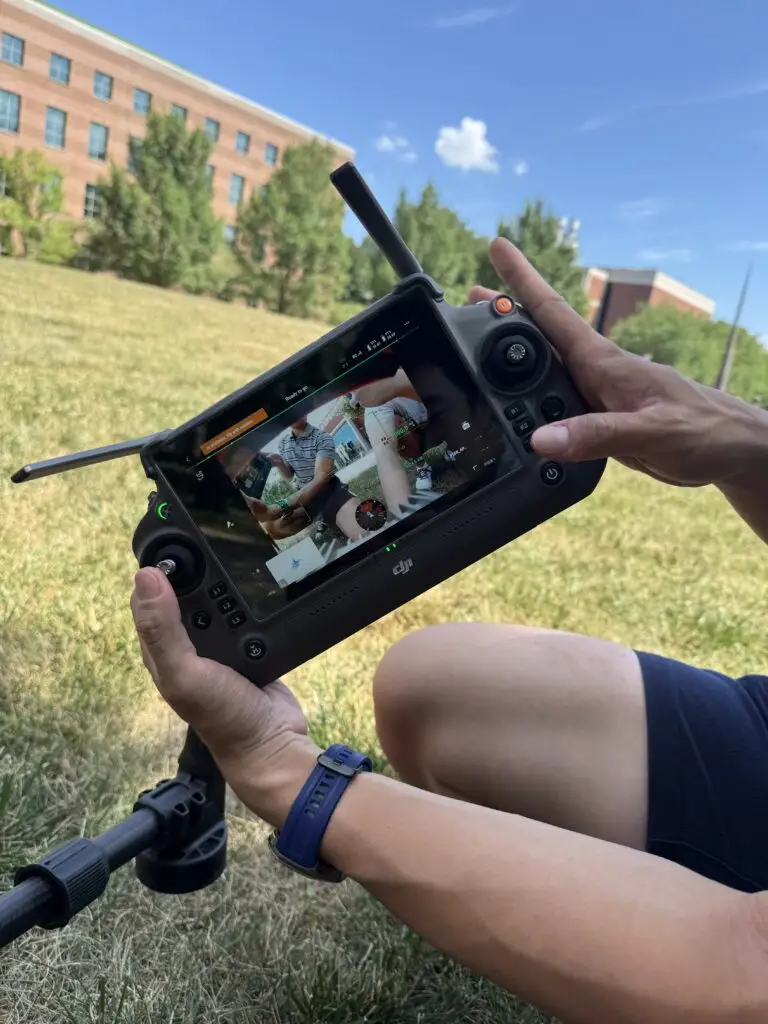
We ran a few dry tests in the lab, confirming we could start and stop image acquisition remotely using Parsec.
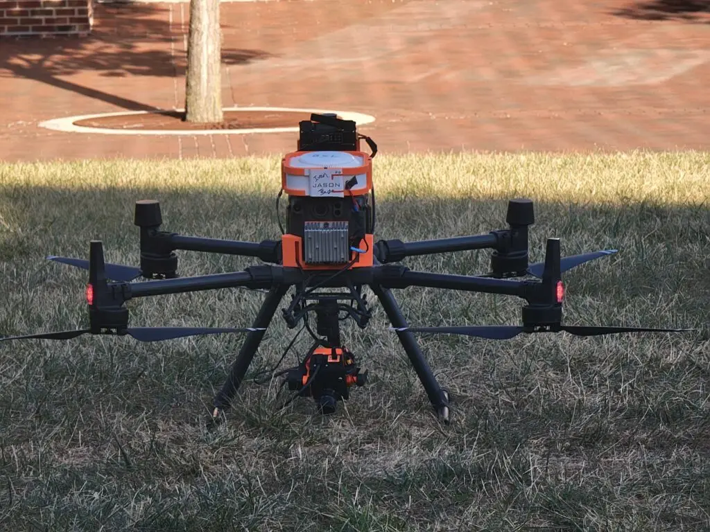
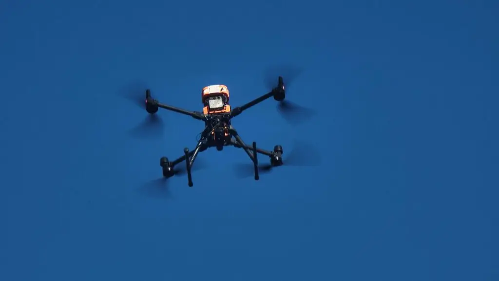
With everything done, our newly formed team gathered together on the Bardeen quad to fly the drone for the first time.
We were able to collect several rounds of data for another student’s manuscript on 27-band camera applications. It was a pretty fulfilling feeling seeing this project take flight, literally. And it was even better doing it with members of the lab I’ve been able to get to know over the last few years, all of whom gathered together to finally make this a possibility.
We have several other test flights prepared for the future, collaborating with different labs that are also running aerial imaging experiments. Unfortunately, there’s not much green in the fall and winter in Champaign, so we’re limited in what we can do right now. However, I look forward to updating everyone on the results!